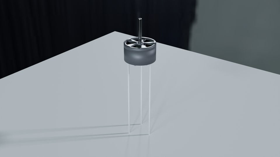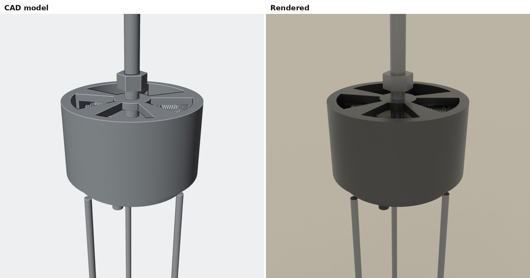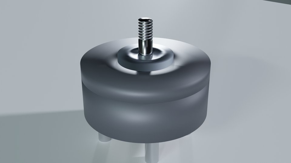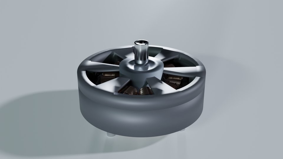
The part

Strip progression
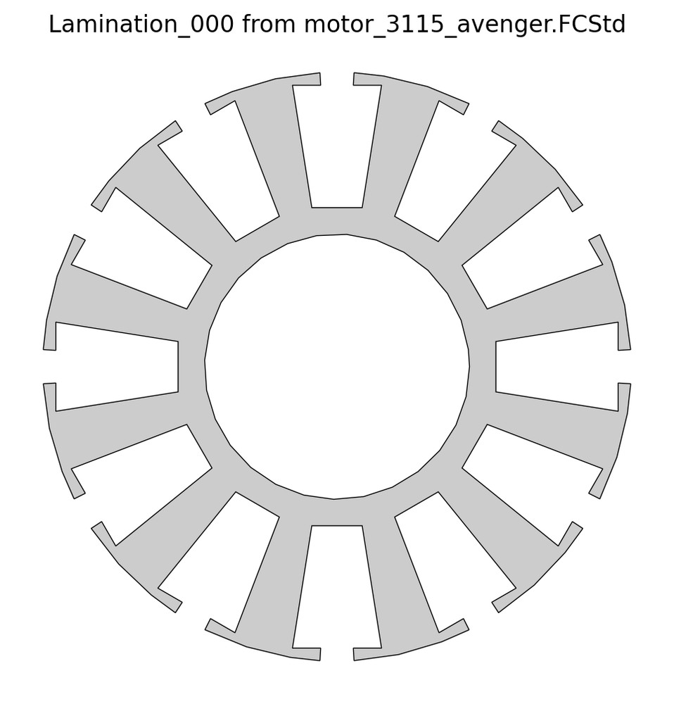
The die that stamps the stator laminations for the 3115 drone motor further down this page: a 12-tooth, Ø31 mm disc in 0.2 mm electrical steel, 75 of which stack into one 15 mm motor core. It blanks them from 33 mm coil strip across six stations at about 3.6 tonnes, and the strip layout, station order, punch geometry and tonnage all come off the lamination itself — so changing the motor re-sequences the die rather than sending it back to the drawing board.
Method exercised
- Strip layout and station sequencing
- Blanking force and press tonnage estimation
- Punch slenderness, bridge and edge-distance gates
- Immutable versioned output with verbatim replay
Emitted
- Die assembly (STEP)
- Wire-EDM strip progression (DXF)
- Machinist specification (PDF)
Capability demonstratedProduct Development →
02Assembly
Welded steel machine base
Pushes: How far weld and fabrication rules can be pushed before they, rather than the designer, decide the member sizes.
The fabricated steel stand a machine bolts down to — roughly 1.2 by 0.8 metres, 19 cut pieces of tube and plate, sized to carry a half-tonne point load. The study treats it as a fabrication problem rather than a modelling one: weld sizing, member slenderness, torch access and saw capability are all evaluated first, and the geometry is whatever those rules allow.
Method exercised
- AWS D1.1 fillet sizing and edge-cap rules
- AISC intermittent-fillet and slenderness limits
- GMAW burn-through and torch-access checks
Emitted
- Cut list
- Mill-bar nesting
- AWS A2.4 weld map
- Staged weld sequence
Capability demonstratedAnalysis & Optimization →
Wire path
Dropout slug
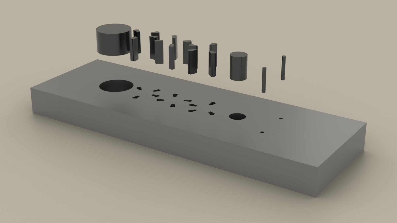
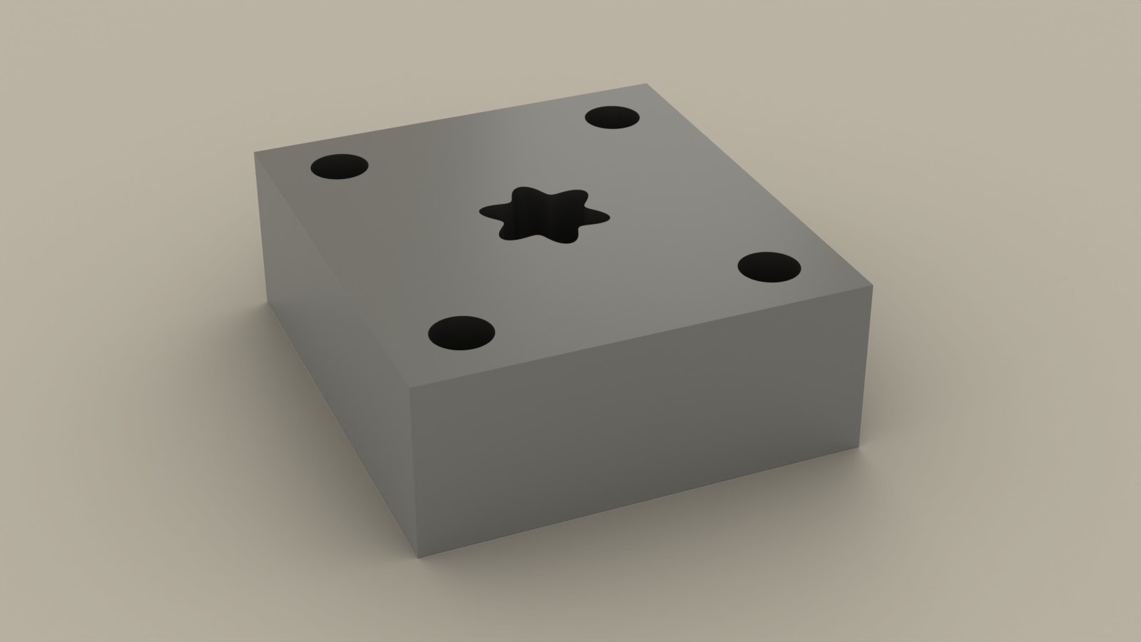
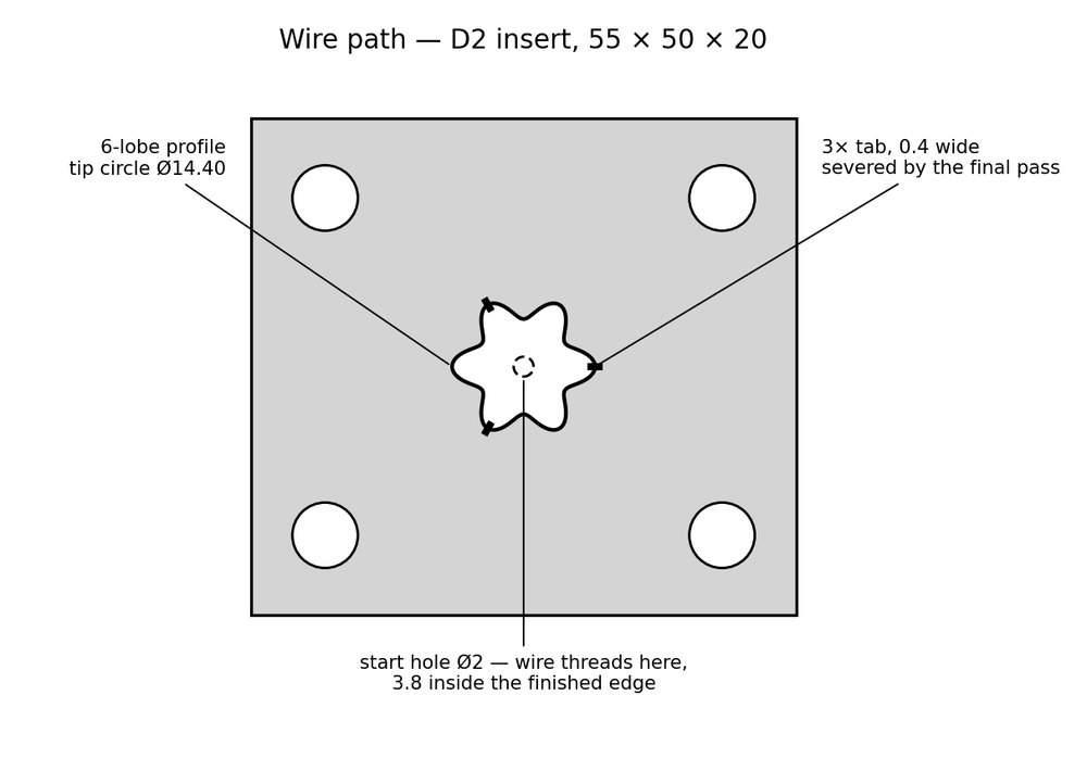
A D2 tool-steel piercing die insert — a 55 by 50 by 20 mm block, corner-bolted into a die-set pocket, with a six-lobe opening cut through it to pierce 1.5 mm sheet. The block is hardened to 60 HRC and ground flat before the wire ever touches it, so nothing after that point can be corrected by machining and the cut plan has to carry every allowance itself. The lobe form stands in for any closed profile — a gear, spline or collet silhouette runs the same machinery.
Method exercised
- Start-hole placement
- Rough / skim-1 / skim-2 offset schedule
- Tabbed dropout retention
Emitted
- As-hardened blank
- Finished insert
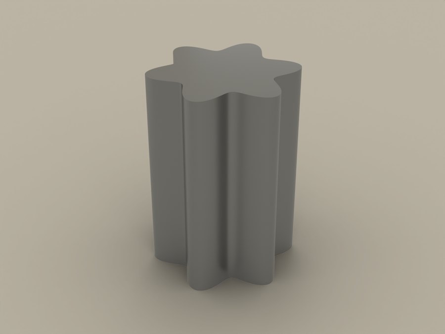
- Dropout slug
Capability demonstratedManufacturing Enablement →
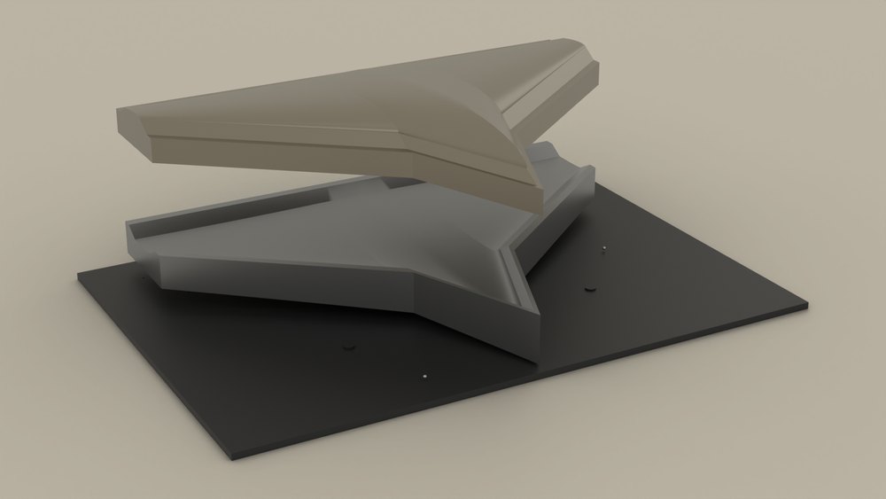
Five delta-wing concepts, each split into an upper and a lower skin at the chord surface so every shell lifts straight off a rigid tool — re-entrant area is zero across all five, and nothing has to be walked out of a cured part. The open question was whether one reconfigurable bed could stand in for those machined tools: a shared plate, a 2 mm spring-steel skin and a field of screw posts, with only a leading-edge rail cut per concept. It holds the surface to 0.29 mm against a 0.30 mm budget, covers 90 to 93 per cent of the chord — and still loses to simply machining the tool.
Method exercised
- Chord-surface split with zero re-entrant area
- Post-field sizing from skin sag and screw resolution
- Leading-edge handover to a machined rail
- Re-set effort weighed against machining the tool it replaces
Emitted
- Machined tool pair per concept
- Pin-bed layout and setup sheets
- Break-even against the machined tool
Capability demonstratedProduct Development →